
Home/Buyer's Guide/What Is CNC Precision Machining? Definition, Process and Tolerance
Definition and principle · six core process steps · accuracy and tolerance · materials · typical applications

"CNC precision machining" is used loosely in sourcing. Some buyers mean "metal parts made on a machining centre." Others mean "parts held within ±0.01 mm." Others mean "machining that ships with a CMM report." Those three readings can differ by 2x in price and imply completely different acceptance criteria. This article works through the basics in the order a buyer needs them — what it is, how it is done, how accurate it really gets, what materials it suits — and then narrows to one product family: optical communication components, which happen to be one of the most direct tests of a shop's precision capability.
Industry terms are used as they are normally used, but each is explained where it appears. By the end you should be able to tell which part of a CNC precision machining quotation is paying for accuracy, and which part is only paying for appearance.
1. What CNC Precision Machining Is
1.1 The definition: you are buying tolerance, not geometry
CNC precision machining is the removal of material from a blank by a computer numerically controlled machine tool, which drives the tool and workpiece along programmed paths to produce a part whose dimensions, form and position all fall inside the tolerances on the drawing.
Two phrases in that definition deserve separate attention. "Inside the drawing tolerance" is capability. "Inside the drawing tolerance on every single piece" is process control. Most of the gap between two suppliers sits in the second phrase, not the first. Making one part at ±0.005 mm and shipping two thousand of them are different jobs.
1.2 The principle: three cutting parameters, three preconditions
The physics is simple. The tool engages at a local stress above the material's strength, and the material shears into a chip that is carried away. Only three parameters can be adjusted directly: cutting speed (spindle rpm), feed rate, and depth of cut. Together they set the material removal rate, the cutting force, and the roughness of the finished surface — which is the logic underneath every machining parameter you will ever see adjusted.
Accuracy, however, is not set by those three alone. It is constrained by three preconditions:
- Geometric accuracy: the machine's positioning and repeatability. For batch consistency, repeatability is the number that matters — positioning accuracy is "can it find the point", repeatability is "can it come back to it". A machine with 3 µm positioning and 1 µm repeatability is worth more than the reverse.
- Stiffness: spindle, holder, fixture and workpiece in series; the weakest link sets the deflection. Most "tool push-off" on thin walls is a fixturing problem, not a machine problem.
- Thermal stability: after four hours of continuous cutting, spindle and ball-screw growth can consume several microns — and the entire allowance on precision work is often only tens of microns.
1.3 Where ordinary CNC machining ends and precision begins
There is no industry-wide definition, but five dimensions separate the two in practice. Decide which column you are buying from before you discuss price.
| Dimension | Ordinary CNC machining | CNC precision machining |
|---|---|---|
| Typical tolerance | ±0.1 mm | ±0.01–0.02 mm; ±0.005 mm on critical features |
| Inspection | Caliper or height gauge, sampling | CMM full-dimension report plus first article (FAI) |
| Environment | General workshop | Temperature-controlled or compensated; isolation for finishing |
| Consistency | Depends on operator skill | Frozen programs, tool-life management, SPC |
| Quotation | Estimated per part | Machine time, setup, inspection and scrap itemised |
2. The Core Process: From a Drawing to a Box of Parts
A typical CNC precision machining workflow has six steps. The steps themselves are unremarkable; what decides the outcome is the control point inside each one — the thing that, if it goes wrong, removes your ability to recover later.
2.1 Step one: drawing review and DFM
The engineer looks at three things: whether the tolerance is functionally necessary, whether the geometry has a cheaper machining sequence, and whether the finish will change the dimensions. The classic case: a ±0.01 mm bore that will later be anodised. An anodic layer of 5–15 µm per side closes that bore straight into scrap. It has to be raised before the quote, not explained after delivery.
2.2 Step two: programming and simulation
CAM turns geometry into toolpaths; simulation catches gouges, collisions and wasted travel. On precision work the real variable is stock allowance: 0.3–0.5 mm left after roughing, 0.05–0.1 mm after semi-finishing, and a single finishing pass to size. Get the allowance wrong and cutting force at the finishing pass springs a thin wall back — the part measures correctly on the bench and does not fit in the fixture.
2.3 Step three: workholding and datums (the most underrated step)
On the same machine, the positional error between two setups is typically 5–20 µm. Stack three setups and a few tens of microns of tolerance are gone. So process design for precision parts comes down to two rules: fewer setups, one datum.
Five faces in a single 5-axis setup, or turning and milling on one mill-turn machine, both buy the same thing: one less setup. That is the real source of the premium on 5-axis machining and mill-turn work — not "more advanced", but one fewer datum transfer.
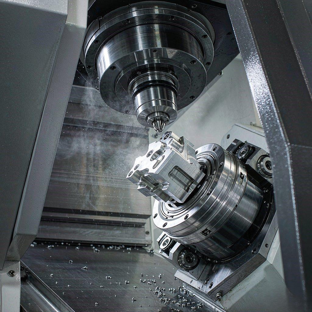
2.4 Step four: roughing, semi-finishing, finishing
The staging exists to control when stress is released. An aluminium blank carries residual stress; cut it in one pass and the part slowly bows. Cut it in three, let the stress out step by step, and take only a light final pass — then the distortion is manageable. Titanium and 17-4PH demand it even more, because heat concentrates at the edge and a heavy pass brings thermal distortion and tool wear at the same time.
2.5 Step five: deburring and surface finishing
Burrs are the most common reason precision parts come back, and the hardest step to automate. A 0.05 mm burr does not register on a caliper, but it will hold two parts apart during assembly. Hand deburring is inconsistent; electrochemical deburring and abrasive flow (AFM) suit internal cavities and cross-holes, priced per part. Finishing has to be settled in advance: plating changes dimensions, blasting changes Ra.
2.6 Step six: inspection and shipping
Inspection on precision work is not "measure it"; it is "measure it traceably". The first article report balloons every dimension on the drawing and records the actual value against each. Production lots are sampled to an AQL or a customer-specified plan, and critical features carry a Cpk. Packaging belongs in the process too — thin-wall parts that distort in transit are a very common cause of "out of tolerance on arrival".
| Step | Purpose | Control point | Typical failure |
|---|---|---|---|
| Drawing review / DFM | Expose unmachinable or expensive features before quoting | Is the tolerance necessary; does finishing move the dimension | Plating eats the tolerance after the part is made |
| Programming and simulation | Turn geometry into a stable toolpath | Stock allowance, path order | Thin-wall spring-back, gouging |
| Workholding and datums | Align the design datum with the process datum | Number of setups, support points | 5–20 µm accumulated per datum transfer |
| Rough / semi-finish / finish | Release stress in stages, hold final size | Allowance per stage, coolant and chip evacuation | Distortion, chatter, surface burn |
| Deburr / finishing | Assembly, corrosion resistance, appearance | Pre-plate condition, coating uniformity | Burr left in, blistering, dimensional drift |
| Inspection / shipping | Prove conformance and traceability | CMM program, sampling plan, packing method | No report; distortion in transit |
3. Accuracy and Tolerance: What ±0.005 mm Actually Means
3.1 Three terms that get mixed up
Accuracy is what the machine can do — a property of the equipment. Tolerance is the deviation the drawing permits — a property of the design. Repeatability is how consistently the machine returns to the same point — a property of the batch. When a supplier says "we hold ±0.005 mm", they are almost certainly quoting machine positioning accuracy, which is not the same as the achievable tolerance on your feature.
There is only one useful question: on this feature, what can you hold, and how do you verify it? A supplier who answers per feature and names the inspection method is discussing CNC precision machining as a process. A supplier who answers "±0.005 mm on all features" is discussing sales.
3.2 Five sources of error
When a part misses the drawing, five errors have stacked: machine geometry, tool wear and deflection, fixturing distortion and location error, cutting heat and machine thermal growth, and measurement uncertainty. Only the first can be solved by buying equipment. The other four are solved by process, fixturing and discipline — which is why two identical machines can produce parts one grade apart.
3.3 Three capability tiers, three price tiers
| Tier | Achievable tolerance | What it requires | Relative cost |
|---|---|---|---|
| General | ±0.05 mm | Standard vice or soft jaws, standard tooling, sampling | 1.0 |
| Precision | ±0.01–0.02 mm | Pre-ground stock, dedicated fixture, full CMM, FAI report | 1.3–1.8 |
| Ultra-precision | ±0.005 mm and tighter | Temperature-controlled room, grinding or wire EDM, multiple setups, in-process metrology | 2–3.5 |
The most useful way to read this table is backwards: decide which tier each feature actually needs, then pay for that tier only. On most parts, ninety percent of the dimensions belong in the general tier and only five to ten features need precision. Calling the whole drawing ±0.01 mm typically adds 30% or more to the price and changes nothing functionally.
4. Common Materials: They Set the Tool and the Finishing
Material decides tooling, parameters, post-processing and scrap rate — and whether all of it can be sourced under one roof, which matters more in CNC precision machining than in general work, because every subcontractor adds one more handover of datum and condition. These eight families cover most precision work.
| Material | Typical parts | Machinability | Watch out for |
|---|---|---|---|
| Aluminium 6061-T6 | Housings, heat sinks, optical module structures | Fast, stable, cheap to finish | Thin walls deflect; deburr before anodising |
| Aluminium 7075-T6 | Load-bearing structure, fixtures, robot arms | High strength-to-weight | Residual stress; distorts as material is removed |
| Stainless 303 | Shafts, fittings, inserts | Free-machining, good finish | Less corrosion-resistant than 304 |
| Stainless 304 / 316L | Medical, food, vacuum, marine | Work-hardens, gummy | Chatter in deep pockets, rapid tool wear, built-up edge |
| Brass H62 / HPb59-1 | Connectors, ferrule sleeves, terminals | Excellent machinability; Ra 0.4 achievable | Lead-bearing grades restricted under RoHS; slender parts bend |
| Beryllium copper C17200 | Spring contacts, conductive springs | Good elasticity and conductivity | Hard to cut after age hardening; dust needs controls |
| Kovar 4J29 | Optical device packages, hermetic bases | Expansion matches hard glass and ceramics | Gummy and work-hardening; sealing faces need cleanliness control |
| Titanium Grade 5 / PEEK | Medical, aerospace, insulation, wear parts | Poor conductivity / abrasive | Heat at the edge; PEEK needs stress-relief annealing |
One practical note: writing the actual grade saves a round of quotation. 304 and 17-4PH differ by more than 2x in material cost, and "stainless steel" on a drawing hands the choice to the supplier — who quotes the cheap one while you inspect against the expensive one.
5. Typical Applications
5.1 Consumer electronics and automation equipment
Phone frames, connectors, robot joint flanges, linear-stage carriages. The common thread is dense features, high volume and cosmetic requirements — the difficulty is cycle time and consistency, not tolerance on a single part.
5.2 Liquid cooling and new energy
Cold plates, water-cooling fittings, battery busbars. The hard part is sealing-face flatness and burrs in the channels: a 0.05 mm burr is enough to stop an O-ring seating. The process detail for that family is in our cold plate machining guide.
5.3 Medical, optics and semiconductor
Surgical instruments, endoscope components, lens mounts, wafer carriers. Requirements are burr-free, cleanable and sterilisable, and surface roughness usually matters more than dimensional tolerance.
5.4 Optical communication components: the hardest test of precision machining
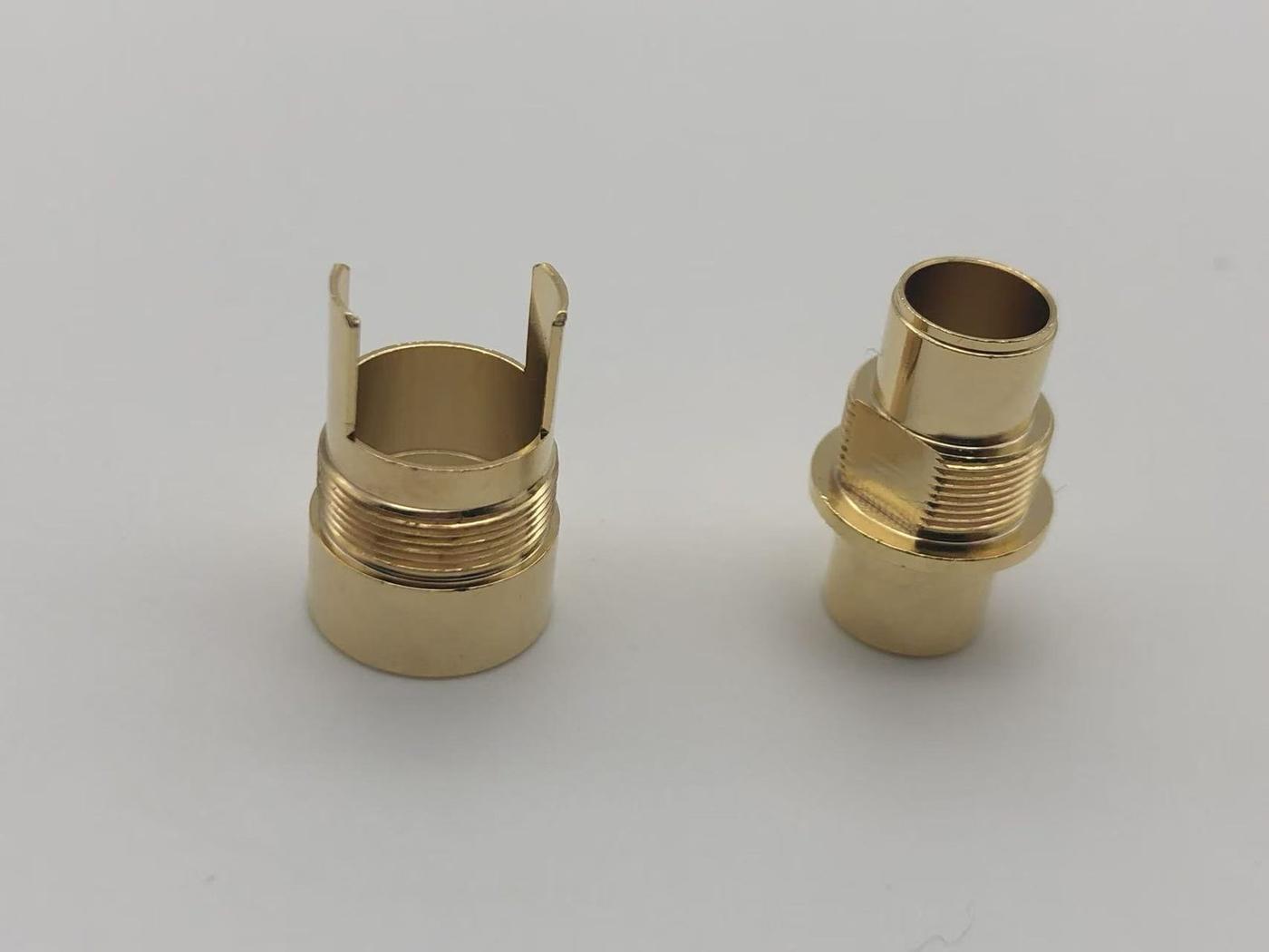
Optical communication components concentrate more requirements per cubic centimetre than almost any other CNC precision machining category: the part is small, but coaxiality, bore roundness, plating thickness and hermeticity all land on the same 20–40 mm body. The difficulty is not the size. It is the three variables that sit outside the drawing dimensions.
- Coaxiality: the inner and outer conductors of a coaxial connector are typically held within 0.01 mm. The consequence of missing it is not that the part will not assemble — it is that VSWR degrades. The part passes, the link fails, and that is the most expensive kind of failure to trace.
- Plating: usually nickel strike plus gold, with 0.3–1.27 µm of gold to the customer specification. Burrs left before plating become blisters and pinholes after it; uneven thickness shortens mating life directly.
- Hermeticity and sealing: TO headers and butterfly package bases must pass helium leak test. Flatness and Ra on the sealing face decide whether the solder wets and climbs evenly — 0.01 mm out here and the leak test fails.
| Part family | Critical features | Typical requirement | Common failure |
|---|---|---|---|
| Coaxial / fibre connector bodies | Step bores, threads, conductor coaxiality | Coaxiality ≤0.01 mm; bore ±0.01 mm; thread 6g | VSWR degradation; thread burrs |
| TO headers / optical module bases | Sealing-face flatness, pin-hole position, Ra | Flatness 0.02 mm; Ra 0.4 µm; hole position ±0.02 mm | Leak-test failure; uneven solder climb |
| Ferrule sleeves / adapter metal parts | Bore roundness, bore diameter, lead-in chamfer | Bore ±0.005 mm; roundness 0.003 mm | High insertion loss; abnormal mating force |
| Module housings / shields | Thin walls, flatness, assembly hole position | Flatness 0.05 mm; wall 0.3–0.8 mm | Assembly interference; shielding failure |
These four families make up a substantial share of the work at Goldencube. What they demand from a shop is not "we have a 5-axis machine" but three things: can you hold a thin wall repeatably, can you control the pre-plate condition, and can you produce traceable data from a CMM and a leak tester. The first two are accumulated process skill; the third is capital.
6. How to Tell Whether a Shop Can Make Your Precision Part
You do not need an audit report. Five questions remove most unsuitable suppliers:
- Ask about the feature, not the accuracy: "What can you hold at this bore?" One question produces a per-feature answer; the other produces a slogan.
- Ask for the inspection equipment list: CMM make and travel, roughness tester, hardness tester, helium leak detector. A shop without a CMM cannot do precision work — there is almost no exception.
- Ask for two comparable parts currently in production: same material family, same complexity. Parts in a sample case were selected; parts in production are process.
- Ask how it will be held: how many setups, where the datum is, how the thin wall is supported. A supplier who cannot answer has probably not run this kind of part.
- Ask whether finishing is in-house or subcontracted: subcontracting is normal; not disclosing it is not. When the plating fails, so does the accountability.
A fuller screening method is in our CNC supplier screening and quotation breakdown guide. If you are still at the prototype stage, prototyping and low-volume production is the closer read. To sanity-check a budget first, the CNC machining cost calculator takes material, process, tolerance, finish and quantity and returns a range in about 30 seconds.
7. Frequently Asked Questions
These four come up most often from buyers and design engineers. Answers are given as ranges rather than promises.
What tolerance can CNC precision machining actually hold?
Three tiers by feature: ±0.05 mm on general dimensions, ±0.01–0.02 mm on fits and critical dimensions, and ±0.005 mm on specific features with a temperature-stable environment, dedicated fixturing and grinding or wire EDM. A blanket '±0.005 mm on all features' is not an engineering statement, and any supplier who offers one deserves a follow-up question.
How much more does precision machining cost than ordinary CNC work?
On the same drawing, the precision tier typically runs 30–80% above the general tier, and the ultra-precision tier 2–3.5x. The extra cost sits in dedicated fixtures, pre-ground stock, full CMM inspection, grinding or wire EDM, and a higher scrap rate — not in a 'better machine'.
What materials are used for optical communication components?
Brass H62 / HPb59-1 is the workhorse (good machinability, takes gold plating); beryllium copper C17200 where spring properties are needed; Kovar 4J29 or 304 stainless for hermetic packages; 6061-T6 aluminium for housings and shields. Plating is usually nickel strike plus gold at 0.3–1.27 µm, to the customer specification.
Can you machine a single piece, and how long does it take?
Yes, from one piece. Prototypes usually run 3–10 days including programming and first-article approval (2–3 days of that is often first-article on precision parts); low-volume production 2–5 weeks; finishing adds 3–7 days. If you have a hard docking date, state it in the RFQ — scheduling priority is set from it.
Request a Quotation
Share your requirements — formal quotation within 24 hours. Your information is used for quoting only and kept strictly confidential.
8. Next Step
If you already have a drawing, send the 2D print, the 3D model (STEP), the material grade, the quantity and your target date. You will get an itemised quotation and a DFM note within 24 hours — including the tolerances we believe could be relaxed to cut cost. Goldencube was founded in Shenzhen in 2012, is ISO 9001:2015 certified, runs simultaneous 5-axis RTCP on every machine and 20+ machining centres (3/4/5-axis and mill-turn), holds ±0.005 mm where it matters, inspects on Mitutoyo CMM, machines from one piece and works under NDA. CNC precision machining, optical communication components, liquid-cooling structures, robot structures and medical/automation parts are routine categories for us — see capabilities and products.
Have drawings? Get an itemized quote within 24 hours
A 2D drawing + 3D model (STEP / IGES) + quantity tiers are enough. Material, machine hours, programming & fixtures, outsourcing and inspection listed separately, plus a free DFM sheet. No drawing review calls.
Send drawings for a quote