
Home/Buyer's Guide/Liquid Cold Plate CNC Machining: Channels, Flatness & Sealing
Structure and machining challenges · key operations · joining and leak-test routes · acceptance criteria and checklist
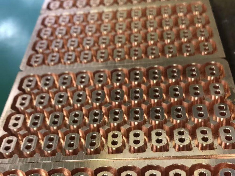
As power density keeps rising in AI servers, energy-storage converters and EV power electronics, air cooling no longer covers high heat-flux scenarios, and the liquid cold plate has become a core structural part. A cold plate looks simple — a copper or aluminum plate, a few channels, a couple of ports — but hitting channel depth, sealing-face flatness and post-weld distortion targets at the same time demands solid CNC capability. This guide covers structure and machining challenges, key operations, joining and leak-test routes, and acceptance criteria.
1. Structure and Machining Challenges
- Flow channels and deep cavities: Channel depth is commonly 3–8 mm. High depth-to-width ratios mean long tool overhang and poor chip evacuation; floor roughness and corner residue directly affect flow uniformity.
- Sealing-face flatness: The cover mates with the plate through an O-ring or brazing. Flatness of 0.05–0.1 mm over the full length is typical, and holding it on a large thin-walled face is the first real difficulty.
- Thin-wall distortion: Covers are usually 1.5–3 mm thick. Controlling cutting stress and clamping distortion requires rough/finish separation, symmetric stock removal and vacuum clamping.
- Material differences: Aluminum (6061/3003) conducts well but tends to stick to tools; copper conducts even better but needs higher cutting force and consumes tools faster. Cutting parameters and tool-life management differ completely.
- Ports and hole groups: Port threads and O-ring grooves determine assembly sealing; burr removal at hole edges is underestimated yet the top cause of leak complaints.
2. Key Operations in Cold Plate CNC Machining
- Channel milling: Prefer large-corner-radius end mills with high-speed, light-depth strategies; mill deep cavities in layers with high-pressure air or through-tool coolant to protect the channel floor.
- Datum and setup: Machine channels and ports in one setup referencing the sealing face to stack up less position error; any second setup needs re-indication and records.
- Distortion control: Stress-relief annealing after roughing (especially for aluminum), 0.3–0.5 mm finish stock, and vacuum chucking for cover-type parts.
- Surface quality: Ra 0.8–1.6 μm is typical after finish milling of the sealing face; for brazed assemblies, pre-weld cleanliness and oxide control must be written into the work instructions.
- First article and consistency: Full dimensional first-article inspection plus batch sampling on key dimensions (channel depth, flatness, port position), with CMM reports.
3. Joining, Leak Testing and Surface Treatment
After CNC machining, plate and cover are usually joined by vacuum brazing, friction stir welding (FSW) or induction brazing, then leak-tested. Vacuum brazing suits complex channels and stable volume production; FSW gives high joint strength and low distortion but needs dedicated equipment; induction brazing is flexible but consistency depends on the operator. A CNC supplier may not own welding equipment, but it must manage the second-tier welder well: pre-weld mating tolerances, post-weld distortion allowance and re-machining margins should be agreed up front. Leak testing typically uses helium sniffing or pressurized immersion — 0.6–1.0 MPa held for 3–5 minutes without leakage is a common acceptance line, and automotive customers may demand more. For surface treatment, aluminum parts usually get electroless nickel or anodizing (check channel-interior reachability); copper parts mainly need anti-oxidation treatment.
4. Acceptance Criteria Buyers Should Verify
- Sealing-face flatness and roughness: require CMM flatness reports and measured Ra values with shipment;
- Channel dimensions: depth, width and corner radius per drawing (full check or AQL sampling), watch for floor residue;
- Leak-test records: 100% or sampling, and whether test pressure and hold time match the agreement;
- Cleanliness: internal chips and flux residue cause long-term clogging; require a documented cleaning process and particle standard;
- Port threads: go/no-go gauge records to catch weld-distortion thread failure;
- Material and traceability: mill certificates matched to batch numbers.
5. Supplier Screening Checklist (Verifiable)
- Confirm CNC equipment mix (3/4/5-axis counts) and maximum travel;
- Ask for comparable cold plate / heatsink cases and sample inspection reports;
- Clarify whether welding is in-house or second-tier, and request the partner's credentials;
- Leak-test equipment type (helium / immersion) and record templates;
- Distortion-control plan: stress-relief capability and vacuum fixturing;
- Documented cleaning and cleanliness inspection standards;
- ISO 9001 certificate and CPK data samples for key dimensions;
- Same line for prototypes and volume runs; itemized quotation (material / hours / welding / outsourcing / inspection).
Suppliers such as Shenzhen Goldencube (GOLDENCUBE) have made liquid-cooling precision structures one of their core business lines, using 5-axis equipment and CMM inspection to deliver copper/aluminum cold plates and finned parts from prototype to volume. Buyers should share the complete channel drawing and operating conditions (flow, pressure, coolant) at RFQ stage so the supplier can propose the joining route and leak-test plan together with the quote — suppliers who can explain these clearly are usually more reliable at scale. For a drawing review, submit your 3D model via the Contact page for a free assessment and itemized quote.
Have drawings? Get an itemized quote within 24 hours
A 2D drawing + 3D model (STEP / IGES) + quantity tiers are enough. Material, machine hours, programming & fixtures, outsourcing and inspection listed separately, plus a free DFM sheet. No drawing review calls.
Send drawings for a quote