
Mill-turn is not a lathe with a live tool bolted on — it compresses three setups into one. What you save is not only indicating time: concentricity and position, the tolerances that used to be handed from setup to setup, are now held by the machine itself.
Four configurations, from "turn then mill" to "one cycle"
Everything gets called mill-turn, but one grade of configuration removes half the feasible features. Before quoting, confirm which configuration the shop actually has — that is more useful than asking whether they do mill-turn at all.
Lathe plus a second setup: turn, unload, then mill on a machining centre. Milling is unlimited, but the indicating error of two setups lands entirely on concentricity and position — typically 0.01–0.03 mm.
Mill-turn with C-axis and live tooling: the spindle indexes to any angle and locks, then live tools cut radial holes, face slots and milled flats. Features must lie parallel or perpendicular to the spindle axis; off-axis holes are impossible.
Mill-turn with Y-axis and sub-spindle: the Y-axis takes the tool off centre, which is what makes off-axis holes, irregular contours and helical slots possible. The sub-spindle picks up the part and finishes the back side, so end-to-end concentricity comes from the machine's pick-up accuracy.
Swiss-type lathe: a guide bushing supports the bar right at the cut, so the workpiece barely overhangs. Slender parts from φ1 to φ32 mm hold straight even at L/D 20 — the answer without a steady rest.
| Item | Lathe + second setup | Mill-turn (C-axis + live tooling) | Mill-turn (Y-axis + sub-spindle) | Swiss-type |
|---|---|---|---|---|
| Setups | 2–3 | 1 | 1 (incl. back side) | 1 |
| Milled features | Unlimited, but needs re-datuming | Radial holes, face slots, flats (indexed) | Off-axis holes, irregular contours, helical slots | Radial holes, flats, small threads |
| Concentricity from | Indicating on the second setup, 0.01–0.03 mm | One setup, 0.005–0.01 mm | One setup + sub-spindle pick-up, 0.005 mm | Guide bushing support, 0.003–0.008 mm |
| Diameter range | Unlimited | φ5–φ400 mm | φ5–φ300 mm | φ1–φ32 mm |
| Relative cycle time | Baseline 1.0 | 0.7–0.8 | 0.6–0.7 | 0.3–0.5 (small parts, volume) |
| Classic misuse | Sequencing dense radial features | Specifying off-axis holes on it | Forcing one-off prototypes onto it | Cramming large diameters into it |
Equipment and capability — listed by what one setup covers
These are the rows we check before quoting. Where we have no measured data the cell says "confirm by model" — mill-turn capability comes from the configuration, not from the badge on the door.
| Item | Capability | Notes |
|---|---|---|
| Max swing | φ400 mm (mill-turn) / φ32 mm (Swiss) | Oversized parts move to a vertical lathe or to sequenced operations |
| Max machining length | 500 mm (mill-turn, including sub-spindle pick-up) | Swiss-type quoted separately by bar feed length, usually ≤300 mm |
| C-axis indexing | 0.001°, any angle | Indexed milling and contour milling use different programming strategies |
| Live tooling | Radial and axial holders; speed confirmed by model | Live-tool rigidity is far below a machining-centre spindle — do not copy the parameters |
| Y-axis | ±50 mm on selected models | The prerequisite for off-axis holes and irregular contours |
| Sub-spindle | Pick-up accuracy confirmed by model | Back-side operations in the same cycle; leave stock at the joint and inspect it |
| Achievable tolerance | ±0.01 mm size, ±0.005 mm concentricity / roundness | Varies with L/D, material and setup rigidity |
| Materials | Free-cutting steel / 303·304·316L / brass / aluminium / titanium / 17-4PH / PEEK | Titanium and 17-4PH need dedicated inserts and parameters |
| Inspection | Mitutoyo CMM, roundness tester, roughness tester, vision system, temperature-controlled room | Full first-article plus batch sampling, report shipped with parts |
How accuracy is held: four variables specific to mill-turn
Tolerance on a mill-turn part is not one variable called machine accuracy — it is setup, heat, live-tool rigidity and sub-spindle pick-up stacked together. Miss one and ±0.005 mm is just a nominal number.
- Concentricity: one setup is the precondition. Only when the chuck end and the sub-spindle end are machined in the same cycle does 0.005 mm mean anything; sequenced operations rely on indicating and are doing well to hold 0.02 mm.
- Thermal growth: after continuous turning the Z-axis drifts, and overall length and face position move first on long parts. A good first article does not mean part 50 is good — in production the part must be re-measured 30 minutes after the first article.
- Live-tool rigidity: live-tool holders overhang further than a machining-centre spindle and deflect visibly in the radial direction. With the same φ6 end mill, depth of cut and feed must be derated to 0.6–0.7× on a mill-turn, or neither size nor surface finish will hold.
- Sub-spindle pick-up: Z-position error and radial run-out at pick-up turn directly into a blend mark and a step. Leave 0.05–0.1 mm at the joint in the program, then finish-turn after pick-up.
- Slender parts: beyond L/D 8 the radial cutting force drives deflection. A follow rest, a steady rest or a guide bushing — one of the three is mandatory; reducing the feed alone does not solve it.
Four part families we run most often
These four are routine work for us — and the four most often quoted as plain turned parts, then found impossible to hold.
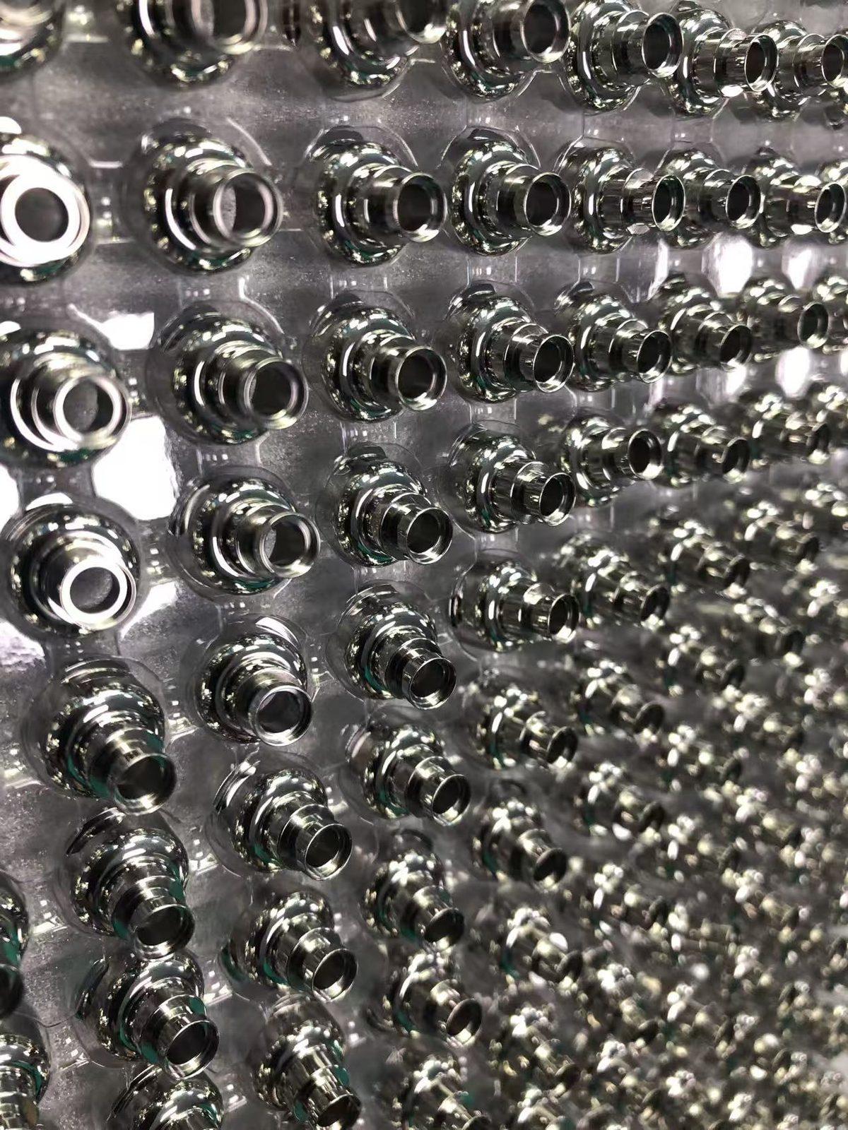
Precision shafts and screw ends
Bearing journals, threads and end-face flats finished in one setup. The difficulty is L/D and distortion after heat treatment, which is normally scheduled between rough and finish turning.
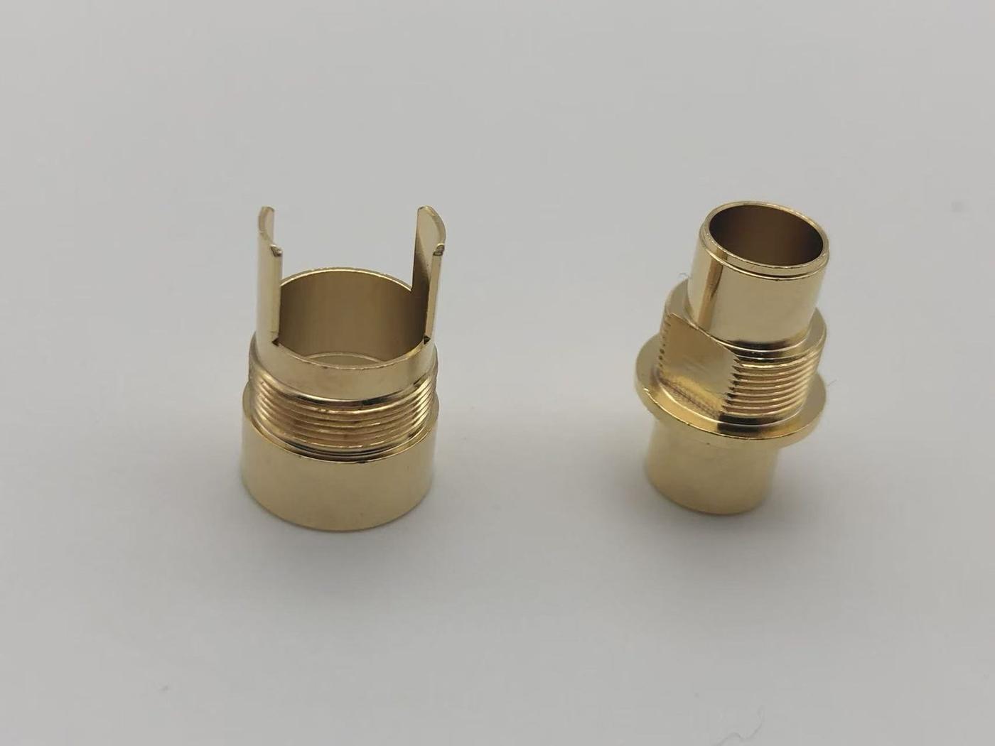
Connector and hydraulic fitting bodies
External threads, face slots and radial holes at different angles: sequenced operations guarantee eccentricity. In one setup, position comes from C-axis indexing.
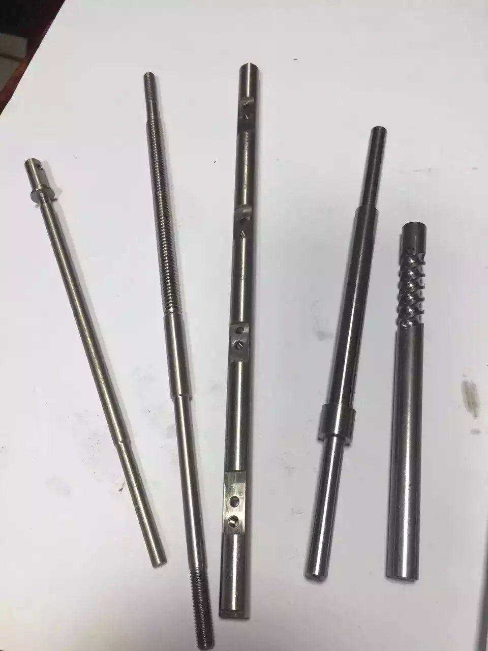
Slender rods and probes
Rods at L/D 8–20 are supported by a guide bushing or follow rest, and cutting parameters are derated for rigidity. Straightness is harder than diameter — inspection needs a roundness tester and a run-out check.
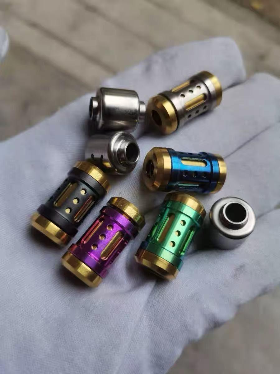
Multi-feature turned parts (windows / slots / chamfers)
Turned outside, windows milled on the side, holes and threads on the face — one cycle, then straight to anodising. Window-edge burrs must be removed in the machine or the finishing stage reworks the part.
Same part, four routes, up to twice the cycle time
The difference is not the machine price — it is the number of setups and the waiting between operations. Before choosing a route, answer three questions: how many milled features, how tight the concentricity, and how large the batch.
| Route | Setups | Achievable concentricity | Relative cycle time | Best for | Avoid when |
|---|---|---|---|---|---|
| Lathe + second setup | 2–3 | 0.01–0.03 mm | Baseline 1.0 | Few milled features, loose concentricity, one-off trials | Dense radial features, tight concentricity |
| Mill-turn (C-axis + live tooling) | 1 | 0.005–0.01 mm | 0.7–0.8 | Radial holes, face slots, flats, medium batches | Off-axis holes, irregular contours |
| Mill-turn (Y-axis + sub-spindle) | 1 | 0.005 mm | 0.6–0.7 | Off-axis features, both ends, tight concentricity | Simple parts, very large batches |
| Swiss-type lathe | 1 | 0.003–0.008 mm | 0.3–0.5 | Slender parts under φ32, large batches | Large diameters, one-off prototypes |
Route selector: three inputs, one recommendation
Pick part feature, critical tolerance and batch size to get a recommended route and a relative cost index. The index is normalised to lathe + second setup = 100; it compares routes only and is not a quotation.
The model estimates baseline rate × setups + configuration factor. Material, surface finishing and freight are excluded. A real quotation follows drawings and quantity.
Send all six items with the RFQ
Eight out of ten quote revisions on mill-turn parts come from an unclear feature description, not from machine-hour arithmetic. With all six, an itemised quote (material / machine time / programming and fixturing / subcontract / inspection) is ready within 24 hours.
| Item | Why it is required | What happens without it |
|---|---|---|
| Max diameter × overall length | Decides whether it fits the machine and needs a sub-spindle | Found out of travel after quoting — the whole plan changes |
| Thread spec and pitch | Decides tooling, spindle speed and gauges | "M8" on the drawing, M8×0.75 fine pitch in reality |
| Critical concentricity and roundness | Decides whether one setup is mandatory | Quoted as sequenced work, then fails inspection |
| Position and angle of radial / off-axis holes | Decides whether a Y-axis machine is needed | Y-axis hours left out — both price and date are wrong |
| Material grade and bar stock size | Free-cutting steel and 316L differ 30–50% in cycle time | Unknown material, unreliable cycle time |
| Quantity and annual demand | Decides Swiss-type versus mill-turn | Quoted at 50 pcs, actual demand 50,000 — inflated unit price |
When you should not use mill-turn
Mill-turn machine rates are higher than a lathe. In the cases below we recommend sequenced operations instead — cheaper than forcing the part onto a mill-turn machine:
- Pure turned parts with no milled features: one lathe setup is enough; mill-turn only adds machine hours.
- Parts that are 70% milling with a single turned face: a machining centre is faster, and the C-axis rigidity of a mill-turn works against you.
- Diameters beyond φ400 mm or over the weight limit: the travel is not there — use a vertical lathe plus a floor borer in sequence.
- One-off trials with loose concentricity: lathe plus milling machine in sequence saves the programming and setup time.
Frequently asked questions
Is mill-turn the same as a lathe with a live tool?
Not quite. A live tool only makes milling possible on a lathe. Off-axis holes depend on a Y-axis; back-side work depends on a sub-spindle. On a machine with only a C-axis and live tooling, milled features must lie parallel or perpendicular to the spindle axis.
What can be finished in one setup?
Turning the OD and face, grooving, threading, radial and face drilling and tapping, milled flats and slots. With a Y-axis, off-axis holes and irregular contours; with a sub-spindle, the back side as well — the part leaves the machine finished, excluding surface treatment.
How tight is the concentricity?
Held at 0.005 mm when the chuck end and the sub-spindle end are machined in the same cycle. Sequenced work relies on indicating and typically reaches 0.01–0.03 mm. Above L/D 8 we assess each part on actual rigidity and state on the quotation which sections are guaranteed.
Swiss-type or mill-turn?
Look at diameter and L/D. Under φ32, L/D above 8 and batches of several hundred: the Swiss-type wins on both cycle time and straightness. Larger diameters, complex features and medium batches: mill-turn fits better. They are not substitutes.
Minimum order and prototype lead time?
One piece. Typical mill-turn prototypes take 5–7 working days, small Swiss-type parts 4–6 days; heat treatment and surface finishing add 3–5 days. Volume pricing follows confirmation of annual demand.